


1. Introduction
The hip joint is one of the most essential weight-bearing structures in the human body. As a result, it is frequently damaged, in extreme instances necessitating total hip arthroplasty (THA). Hip implants can vary in design but generally consist of a stem attached to the femur, a head connected to the stem, an acetabulum attached to the pelvis, and a polyethylene insert into the acetabular component. The area between the head and the acetabulum is known as the bearing surface: this is where the joint moves, leading to friction and wear. They may fail for many reasons, resulting in adverse clinical and functional effects, including periprosthetic joint infection, aseptic loosening and osteolysis, dislocation or instability, and adverse reactions to metal debris and bone or implant fracture. Wear debris that separates from the implant surfaces is the common cause of aseptic loosening.1,2 The effects of Al2O3 particles on aseptic loosening are still unclear, although studies have shown that Al2O3 particles may induce autophagy formation.3,4
Metal heads with a polyethylene insert are a successfully used bearing combination in THA. Cobalt-chromium-molybdenum alloys are widely, but not exclusively, used for head prostheses due to their high mechanical resistance and good corrosion properties in body fluids. However, concerns remain with wear debris and metal ion release, which initiate a negative response in the surrounding tissues. Acetabular insert wear was identified as an essential factor influencing the durability of total hip arthroplasty.5 Conventional ultra-high molecular weight polyethylene used as the insert material is considered the weak point for long-term THA durability. The introduction of highly cross-linked polyethylene (HXLPE) improved functional parameters6–9; however, polyethylene is still considered a weaker point in THA, with a significant threat being oxidative embrittlement.8 In addition to the load-bearing surfaces, the wear of hip joint implants may also affect modular joints due to micro-movements.10 In the running-in phase, the first million cycles (walking) show the highest wear rates, usually covered by the first 12 months. Later, the wear rate levels out and becomes stable.11 Sobociński12 proved that the friction coefficient for the polyethylene-CoCrMo tribo-pair is much lower in the Al2O3-Al2O3 and CoCrMo-CoCrMo systems.
Abrasive wear can be divided into those where the abrasive medium is loose as it passes over the testing surface (commonly referred to as three-body abrasion) and those where the orientation of the abrasive media is fixed as it passes over the testing surfaces (widely referred to as two-body abrasion). Two-body abrasive wear often turns into three-body abrasive wear, where the abrasive particles act as abrasives between the surface,13 where these trapped particles are free to roll and slide. In this case, mechanical wear depends on the abrasiveness of the particles, the surface strength of the sliding surface materials, and the ejection probability of third-body particles.14 Examples of three-body abrasion would be wear caused by hard contaminants or debris trapped between moving surfaces. The metal counterpart in polymer/metal trio-pairs may also suffer severe wear if hard particles are present. However, some research has focused on this phenomenon. CoCr is particularly susceptible to scratching by trapped particles due to its hardness being half that of ceramics.15 The femoral head diameter also played a crucial role in the wear.16
Every year, many patients need to regenerate damaged or diseased bone tissue. For this reason, tissue engineering has gained extraordinary attention as an alternative strategy for treating and restoring bone defects. Porous bioceramics designed to resemble the structure of bones are used as orthopaedic implants in bone surgery to repair and reconstruct diseased or damaged bone. Filling the pores of porous ceramic material with a material that gradually biodegrades in the body promotes overgrowth with biological tissue.17 Composition and structural characteristics, including porosity and pore size, play an essential role in the success of tissue-engineered structures.18 Alumina is widely used as a substrate for bone tissue engineering applications.19–21
The analyses indicate that studies are necessary to further understand the mechanisms of wear and corrosion occurring in hip joints, particularly under conditions of additional impacts. This applies, for example, to situations where the treated patient already has a previous treatment history that may affect the success of the THA procedure.
2. Background
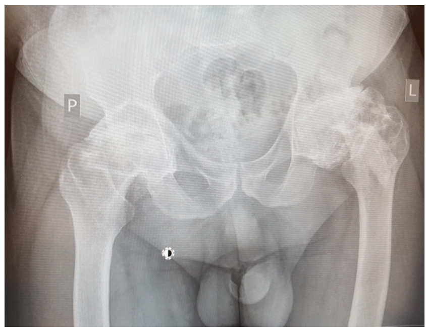
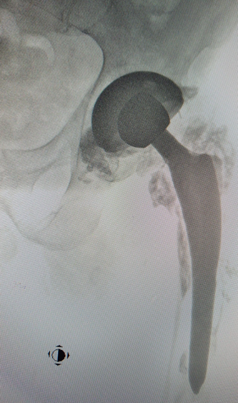
A 35-year-old man suffering from necrosis of the femoral head of the left hip joint underwent surgical treatment consisting of drilling the necrotic head and filling the femoral neck with bioceramic elements (Fig. 1). The porous bioceramic material had the following chemical composition: 97% Al2O3, 2.5% MgO, and 0.5% CaO.17 The manufactured material (open porosity, 70–80%) was characterised by external and internal pores with pore diameters between 100 and 800 μm. The outer and the inner pores were filled with healthy bone tissue adherent to the ceramic material. Bieniek17 the material was used to fill bone cysts and postsurgical or trauma-related bone defects.

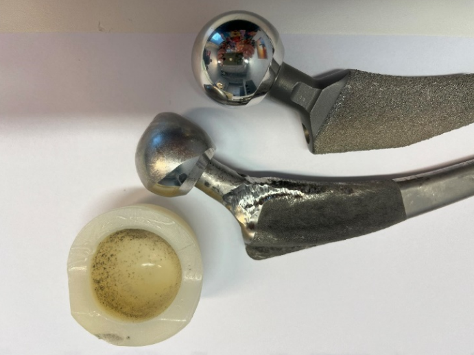
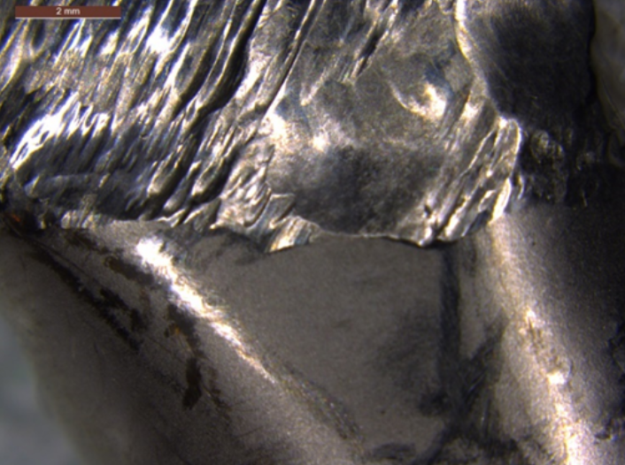
Twenty-seven years later, due to the development of the secondary degenerative disease of the left hip joint, the patient underwent implantation of a total hip joint replacement in which metal/polyethene articulation was used, and ceramic fragments were carefully removed intraoperatively. In this case, a protocol of rinsing the operated joint with an electric pulsation system was used during the revision procedure, as in the case of PJI (periprosthetic infection). Six years after this procedure, the patient was observed to have deformation of the metal head of the endoprosthesis, appearing in control X-rays with relatively minor changes in the thickness of the polyethylene (acetabular insert). The head deformation was accompanied by defects that were visible in the form of radiolucencies located in the third, closer to the femur and in the area of the lower pole of the acetabulum (Fig. 2). The patient reported increasing pain in the left hip joint (increasing with weight bearing), and therefore qualified for revision surgery. The examination revealed severe macroscopic deformation of the metal head of the endoprosthesis, the formation of extensive defects in the proximal part of the femur (greater and lesser trochanter), with perforation of the femur and loosening of the stem of the primary endoprosthesis, as well as bone cysts in the periacetabular area (without destabilisation). The cavities were filled with dark content (specific to metal abrasion products), indicating severe metallosis and the metal neck of the femoral stem was severely scratched. Intense contamination of the polyethylene surface of the insert of an unknown origin was also observed (Fig. 3,4). The elements of the primary endoprosthesis removed during the procedure were subjected to further macroscopic and microscopic examination.


3. Research methods
Macroscopic examinations were conducted utilising a Leica M205A stereoscopic microscope. X-ray analysis of the endoprosthesis cup was performed using a Nikon/Metris computed tomography scanner, model XT H 225 ST. Observations of the element were carried out at a scanning resolution of 45 µm on three virtual cross-sectional planes of the 3D model obtained from a tomographic examination. Microscopic studies combined with EDS analysis were performed using a Phenom XL scanning electron microscope (SEM). 3D measurements were made using an Atos Q 12M accurate 3D scanner with blue light technology. This model, designed for industrial use, allows 12 million points per scan with a point distance of 0.03 – 0.12 mm.
4. Research and discussion
4.1. Macroscopic examinations
The macroscopic analysis revealed that the polyethylene surface was contaminated with particles of different sizes embedded in the endoprosthesis cup’s sliding surface. A sample stereoscopic image of such particles is presented in Figure 5. Observations at higher magnifications showed that their embedding in the surface was related to the formation of numerous cuts in the polyethylene surface, which proves their deep anchoring in the polyethylene surface. A similar macroscopic image of ceramic particles embedded in the surface of the polyethylene insert, formed after the fracture of the ceramic head of the endoprosthesis, was observed by Kampf et al.22 And Hasegawa et al.23 In the first case, this led to dramatic wear of the steelhead of the endoprosthesis, which corresponded to a weight loss of 48.1g in the form of outstanding steelwear products released into the surrounding tissues.22
_stereoscopic_view_of_the_acetabular_surface_with_numerous_embedded_foreign_particles._b.png)
Shen et al. found that the anchoring of hard particles in the friction area affects the tribological wear occurring in the endoprosthesis area. Shen et al.24 foundiction coefficient of rubber/stainless steel tribo-pairs with Al2O3 particles shows different trends under conditions without particles and with various particle sizes. Considering the nature of the wear occurring in such a case, it should be regarded as two-body abrasive wear.
Hard particles embedded in the polyethylene insert will exhibit a “grinding wheel effect”, which can result in rapid wear loss on the metal counter surface. A similar effect was observed in the rubber/steel pair.24,25 Shen et al.24 showed that hard particles can significantly increase the wear of a stainless-steel ball due to the ploughing effect. At the same time, it was found that the impact on wear increases with the size of the abrasive ceramic particles (abrasives). Pintaude et al.26 determined that the friction coefficient is higher when the metal being tested is soft because the penetration of abrasive particles into the surface increases ploughing during friction. The results showed that hard particles could be embedded into the tribo-pairs and accelerate the wear of the cobalt-based satellite alloy.27 Due to the high attack angle of many particles in such a system, fixed-particle grooving typically generates wear rates about ten times greater than comparable analyses with free abrasives.28
4.2. X-ray analysis of a polyethylene insert
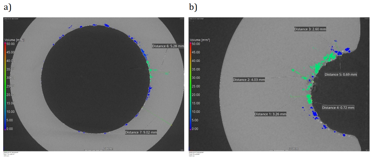
Since particles embedded in the acetabular surface were observed during the macroscopic examination, X-ray tomography tests were performed. This method allows you to identify areas of variable density. The density of alumina ceramics is approximately four times higher, and that of metallic materials is approximately eight times higher than that of polyethylene.9 This allowed us to visualise the foreign particle distribution and depth of deposition. To determine the chemical composition of these particles with different densities, it was necessary to isolate individual particles from the surface and, in the next stage, analyse their chemical composition using the EDS method.
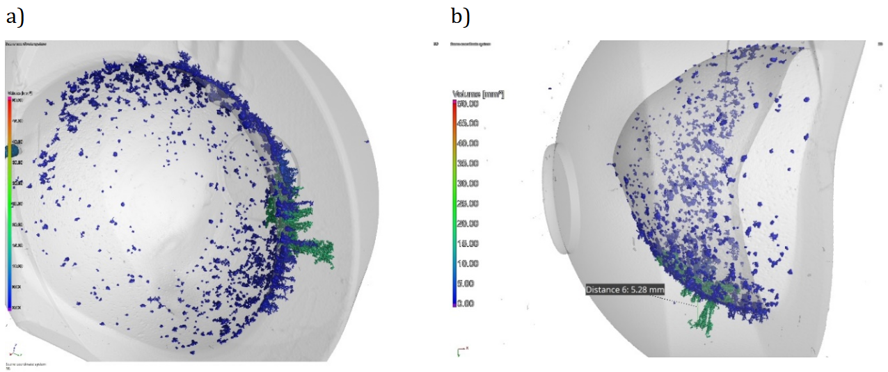
Based on observations of 3D and 2D computed tomography scans, it was found that the accumulation of particles was most significant in the upper part of the acetabulum (Fig. 6,7). The concern, in particular, is particles with a larger volume of approximately 15 to 20 mm3. Measurements taken in these areas at various cross-sections showed that some particles were as deep as 6.5 mm. In the near-surface areas, particles with smaller volumes of up to 10 mm3 were located. The size of selected larger particles located near the surface was estimated to be approximately 0.7 mm. Shen et al.24 showed that the size of ceramic particles affects the loss of a ball made of stainless steel under friction conditions, and they observed the most significant wear in the case of large-sized particles.
_and_lateral_(b)_plane.png)
_and_lateral_(b)_plane.png)
The observations made using a stereoscopic microscope indicate that, during the service life of the joint, these foreign particles were “pressed” into the polyethylene surface. The range of forces acting on the hip joint is essential here. The hip biomechanics are well known, and it is generally accepted that Pauwels’ balance combines body weight, muscle work and the response at the junction of the femoral head and the acetabulum.9 When the patient walked, the load on the head of the femur could reach seven times the human body weight.9 The patient’s weight of 80 kg means that it was over half a ton. These high forces transmitted through the joint were sufficient to move high-hardness particles in the area of the softer polyethylene insert. All the more so because, as observed at the stage of macroscopic tests, these particles led to cutting the polymer surface.
4.3. SEM microscopic examination combined with EDX analysis
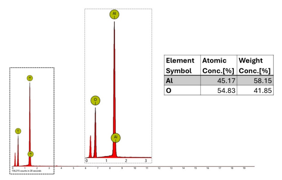
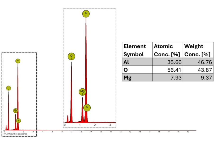
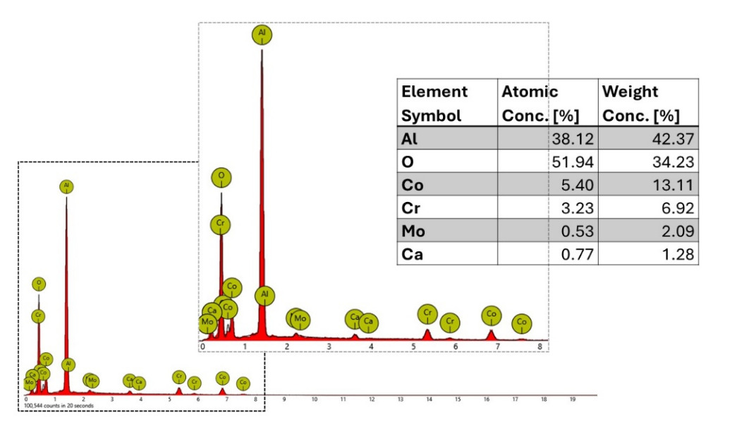
The presence of external third bodies inside the tribological system was confirmed by SEM/EDS analysis. A general view of sample particles isolated from the polyethylene surface is shown in Figure 8. The spectra of characteristic radiation obtained from both particles are presented in Figures 9 to 12. They showed heterogeneity of chemical composition resulting from mixing wear products, but the results were repeatable. EDX analyses showed that the aluminium and oxygen content in the particles were similar to Al2O3. In both studies, in which aluminium and oxygen were observed as the only elements, the composition is close to stoichiometric for corundum ceramics. Analyses performed on the first researched particles showed magnesium and elements typical of aluminium oxide. Bieniek17 points out that porous ceramics based on aluminium oxide also contain MgO and CaO.17 The presence of calcium was observed in analyses performed on the second tested particle, in which wear products of the head of the endoprosthesis made of the Co-Cr-Mo alloy were also found. It is worth paying attention to the relatively low cobalt content with a significant share of chromium and molybdenum. Koronfel et al.29 emphasise the preferential dissolution of cobalt according to a mechanism similar to dealloying. This also explains the non-stoichiometric content of cobalt concerning other elements from the Co-Cr-Mo alloy during its degradation.


4.4. Metallographic examination of the endoprosthesis hea2d
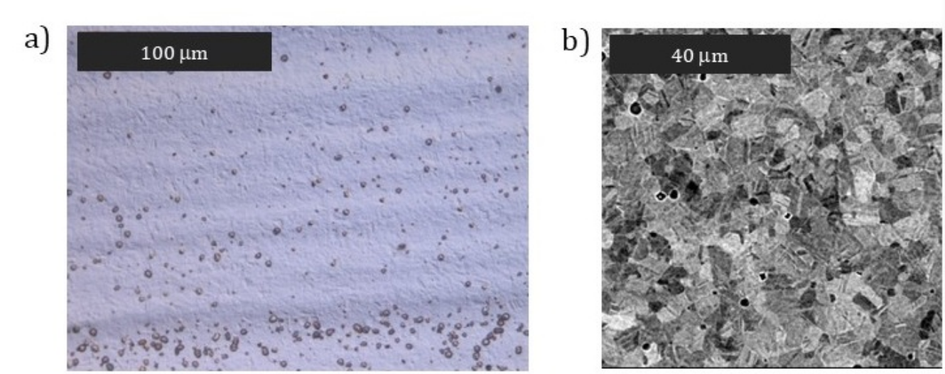
To exclude the influence of poor quality material used for the endoprosthesis head, metallographic tests were performed. The microstructure of the tested material was typical for wrought alloys. Excellent austenite grains with banded carbides were visible (Fig. 13). The high chromium content favours the formation of mainly M23C6 type carbides, but chromium-rich can also be M7C3 and M3C2 type carbides.30,31 In the surface region, no changes in hardness were observed related to weakening or strengthening of the material due to deformation (Fig. 14). At the same time, the average hardness of the material was high and also typical for these alloys. No microstructural causes were found that could contribute to reduced abrasion resistance of the endoprosthesis head.32,33
_visible_banded.png)

4.5. Quantitative assessment of the degree of deformation of the endoprosthesis head (3D scanning)
The cobalt structure (HCP) should ensure low wear and hardness of its cobalt alloys,34 and the hardness of corundum ceramics is 15.7 GPa.35 The hardness of cobalt wrought alloys depends on the grain size and is approximately 4 GPa, which is four times lower than the hardness of alumina ceramics.34 Grain refinement favours the higher hardness of these alloys, which is related to grain boundary strengthening and commonly described as the Hall-Petch effect. Meanwhile, macroscopic examinations showed dramatic destruction of the endoprosthesis’s metal head.
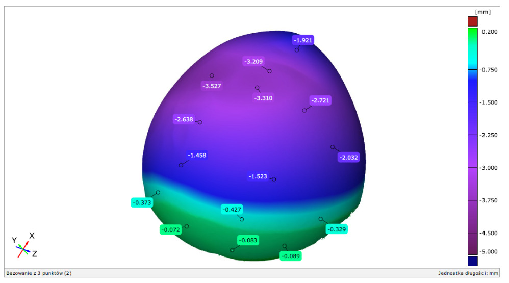
More information about quantitative analysis can be obtained from 3D measurements made using a 3D scanner, the results of which, in the form of a deviation map, are presented in Figures 15 and 16. 3D scanning is an advanced process that allows the transfer of an actual three-dimensional shape into a digital form. The study compared the tested post-exploitation endoprosthesis with a new endoprosthesis head with the same geometry. This allowed for determining material loss by finding the difference in geometric dimensions. In this study, the damage of a Co-Cr-Mo alloy ball was associated with the value of K=(R-r), where R and r are the radii of the unused head and the head with a worn surface, respectively. The analysis of the scanning results shows that the K parameter characterising the material loss exceeded 3 mm in many places. The most considerable losses were observed on the top of the head. This is the place with the most significant accumulation of ceramic particles embedded in the polyethylene surface. The lower area of the head, which did not cooperate with the acetabular cup, did not show any material loss, confirmed by macroscopic observations. The differences that exist are solely due to the tolerance of the element.

4.6. Microscopic evaluation of friction surfaces (SEM)
Wear and corrosion synergistically affect the endoprosthesis’s bearing surfaces, i.e. tribocorrosion, which may involve material losses.36 Studies are available for as-cast CoCrMo alloys,37–39 which found that the wear rate of cast CoCrMo depends on the type and size of abrasive particles, their hardness and volume concentration.37,38 Larger particle size, higher hardness and higher volume fractions of the abrasive result in higher material wear rates.37 As exemplary for the SiC/0.9% NaCl environment, it was found that the wear mode showed a transition from grooving to rolling abrasion as the load decreased and the abrasive volume fraction increased.38 The microstructure of the tested material is also essential. Cawley et al.39 A higher carbide content in the microstructure of cast CoCrMo alloys promotes lower wear.
The microscopic observations of the head surface of the endoprosthesis made of the CoCrMo alloy indicate that the worn head surface showed typical features of abrasive wear (Fig. 17). The relatively deep abrasive grooves near the edges of the worn surface can be observed in the low magnification of the SEM images. Microploughing is the dominant erosion mechanism caused by hard third-body particles, in which the material is not removed from the surface but moves to the side of the erosion groove.40However, macroscopically, the wear features showed different damage characteristics due to differences in the local contact pressure. The extent and shapes of the wear grooves indicate a significant difference in the movements and size of the abrasive particle.41,42 Those detached particles could form third bodies and be rejected from the contact or spread on the metal surface. Topographic measurements were used to describe wear. Analyses performed on the surface, shown in Figure 18, indicate that the depth of these scratches was up to approximately 2 µm. A representative measurement taken along one of the lines is shown in Figure 18c.
_surface_morphology_of_the_endoprosthesis_head_in_and_outside_the_area_of_the_contact_w.png)
_morphology_of_the_endoprosthesis_head_surface__sem__b)_3d_profile_of_the_endoprosthesi.png)
5. Discussion
The literature reports instances of premature polyethene wear. However, these are mostly related to metal/polyethylene joints and, in rare cases, ceramics/polyethylene.43 From a clinical point of view, the most common cause is incorrect joint alignment or acetabular-femoral conflict. In the past, polyethylene was subject to premature degradation due to its poor quality and oxidation facilitated by sterilisation.
There have also been reports of damage to the ceramic components of hip joint endoprostheses. When ceramic/ceramic articulations were utilized, they were commonly damaged, whereas ceramic/polyethylene articulations were used far less frequently.44,45 In such a situation, damage to ceramic elements can potentially leave ceramic particles during the revision procedure and further damage the friction surfaces.22,23,46–49 The presence of ceramic particles resulting from fatigue fracture of the ceramic head may lead to osteolysis around the acetabulum, as observed by Nho et al.45 Similar observations were reported by Hasegawa et al.,23 as well as by Matziolis et al.47 In turn, Traina et al.46 emphasize that fragments of a cracked ceramic head left in the joint space act as an abrasive, quickly leading to catastrophic wear and damage of the new endoprosthesis with a metal and polyethylene insert used during the revision procedure.
For this reason, the literature emphasises the need for thorough synovectomy after rupturing ceramic endoprosthesis elements.46,50–52 Rambani et al.51 reviewed the literature on clinical practices for ruptured ceramic endoprosthesis bearings. Trebse et al.53 Postulate the use of ceramic-on-ceramic articulation in revision cases after damage to ceramic elements.
The presented work contains unique results because the causative factor of implant damage was particles of porous alumina bioceramics implanted 27 years earlier, which were released from the bone tissue during the endoprosthesis implantation process. These tiny fragments of bioceramics were too small to be visible to the naked eye of the operating surgeon. Their different properties and morphology cause such an unusual pattern of damage to the metal head while maintaining relatively minor damage to the polyethylene insert, and they also became responsible for metallosis.
As research by Ribeiro et al.54 indicates, the presence of ceramics in the area of interacting surfaces is not sufficient for accelerated wear to occur. At the initial stage, they observed increased wear of composites: CoCrMo with the addition of ceramics resulting from additional abrasive interactions related to the penetration of torn-out ceramic particles into the friction area. However, as wear progressed, they observed the gradual removal of these particles from the friction surface, which ultimately did not result in increased wear. In the presented research, the critical factor was the embedding of ceramics in polyethylene, as well as a specific, closed area of friction that prevented ceramic particles from escaping the location of the artificial joint.
6. Conclusions
The main wear mechanism of the endoprosthesis head was the abrasive wear caused by the hard particles as a third body, which were embedded in the polyethylene acetabulum as a result of the forces acting on the joint. In the situation we examined, the particles were immovably affixed to the polyethylene insert, escalating head wear. Consequently, the head of the cobalt alloy endoprosthesis experienced significant deterioration, leading to severe metallosis in the surrounding tissues. There were no causes from the material used for the endoprosthesis head that would reduce its resistance to abrasion. The described case is unique due to the origin of ceramic particles that caused damage to the endoprosthesis components.
The presented results have great practical significance. They indicate that great care should be taken when using polyethylene components, as previous surgeries involved using porous bioceramics to fill damaged bone fragments. Alloplasty, in such a case, carries a high risk of complications. The complete elimination of ceramic pieces remaining in the joint space is vital in reducing the risk of another failure. While removing larger fragments seems relatively straightforward, their complete removal becomes virtually impossible in the case of smaller ceramic particles that are invisible to the naked eye. The presented case and conducted research indicate that determining the benefits and effectiveness of using such systems requires further study. Each operation requires an individual approach, and the location and extent of existing ceramic fillings used in tissue engineering should be considered.
CONFLICTING INTERESTS
MarL, ZS, MM-K and MacL declared no conflict of interest.
FUNDING
This research received no specific grant from any funding agency in the public, commercial, or non-profit sectors.
INFORMED CONSENT
Informed consent was not obtained in the present study because the study involved an endoprosthesis.
ETHICAL APPROVAL
Ethical approval was not obtained in the present study because the study involved an endoprosthesis.
CONTRIBUTORSHIP
MarL was a major contributor in writing the manuscript, data collecting, analysing data and researching literature.
MacL performed and monitored the biomechanical testing and data collecting
ZS analyzed the data
MMK researched the literature and analysed the data.
All authors reviewed and edited the manuscript and approved the final version of the manuscript.